
Optimization and Verification of CO2 Separation and Recovery Equipment
For CO2 separation and recovery equipment, there are requirements such as low energy consumption, equipment miniaturization, and low cost.
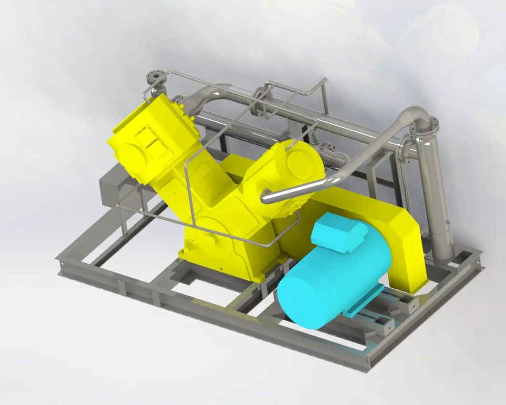
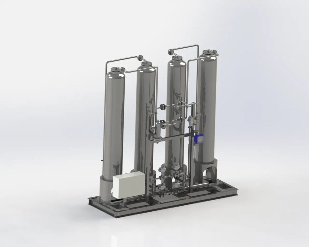
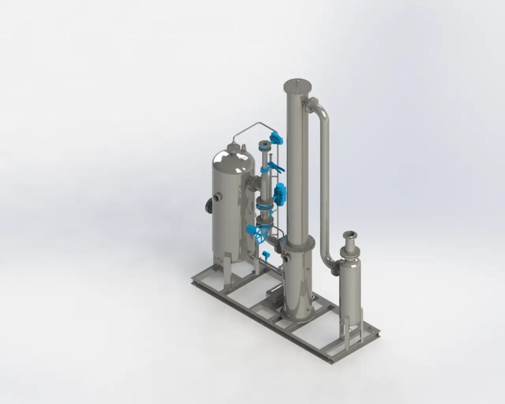
CO2 separation and recovery equipment mainly consists of four parts: absorption tower, regeneration tower, regeneration heat exchanger and reboiler.
These requirements are met by optimizing the four main components and process design, and improving thehttps://www.yitan2010.com/what-are-the-key-differences-between-absorption-towers-and-regeneration-towers-in performance of the absorbent liquid.
Figure 2 shows the development, verification and application process of CO2 separation and recovery technology. Scale up from laboratory scale to pilot scale and further to pilot scale while making appropriate use of process simulation and numerical fluid analysis, and reflect the knowledge gained to design real-scale equipment. Among them, the most important one is the verification on the pilot plant installed at Sigma Electric Power Ariake’s Mikawa Power Plant (Omuta City, Fukuoka Prefecture) (output 50MW).
Development, verification and application process of CO2 separation and recovery technology
While making full use of process simulation and numerical fluid analysis, we will expand the scale and apply the developed technology to the actual-scale device design through verification on the Sanchuan pilot plant.
The pilot plant was installed in 2009 and has the ability to process a portion of the power plant’s exhaust gas and separate and recover CO2 at a rate of 10t/day. This pilot plant was used to verify the system performance, actual exhaust gas state, and the impact of impurities contained on the performance of the absorbent liquid, as well as operability, applicability, and maintainability, and the results were applied to a real-scale device⑴.
For example, in order to supply the heat required for the reaction in the regeneration tower, a part of the steam used for power generation is generally extracted as a heat source. However, when the amount of waste gas to be treated is huge, the heat supply required is also very large, which will lead to a reduction in power generation efficiency. . In order to prevent this, it is necessary to develop an absorbing liquid with smaller reaction heat, adopt a heat recovery process and optimize the design of the regeneration heat exchanger, thereby increasing the recovery heat in the device.
In addition, in the chemical absorption method using an amine-based absorption liquid, the waste gas after recovering the CO2 discharged from the absorption tower into the atmosphere contains trace amounts of amine components derived from the absorption liquid, which may have an impact on the environment. Therefore, on-site surveys of this exhaust gas and development of technologies to reduce the emission of amine components are also being carried out.
CO2 separation and recovery demonstration equipment
Toshiba Energy Systems built a large-scale demonstration facility near the Mikawa Power Plant to separate and recover CO2 from the exhaust gas of the power plant (Figure 3). After the construction started in February 2018, equipment delivery and installation began. After trial operation, it was officially put into use in October 2020 (2). Figure 4 shows the relationship between this demonstration equipment and the Mikawa Power Plant.
The construction and operation of CO2 separation and recovery demonstration equipment were implemented as part of the Ministry of the Environment’s “Environmentally Friendly CCS Demonstration Project,” and the project was adopted by many companies including Mizuho Research & Technology Co., Ltd. (currently Mizuho Research & Technology Co., Ltd.) . In addition, Toshiba Energy Systems is responsible for the design, construction and operation of CO2 separation and recovery demonstration equipment.